The 3 Pillars of Laser Production
Article was written by Bret Fellows. Bret Fellows is a Laser Technical Training Specialist for Cincinnati, Incorporated
A growing number of manufacturers and fabricators are turning to lasers to boost production and enhance metal processing services. These machines are ideal for meeting both short and long-run production requirements while providing the flexibility to adapt to any economic changes on the horizon. Reliable, fast, and versatile, lasers use less energy, process thick material, and can cut complex shapes with precision.
Regardless of type, size, or brand, lasers represent a serious investment and it’s important to fully maximize their features and capacity. To get the most out of your equipment, it’s important to understand the three key pillars of laser production: Machine Operation, Program Operation, and Process Operation.
Machine Operation
Each piece of equipment on the shop floor is designed to operate optimally when properly maintained and used as intended. And there are several areas to consider for optimizing the performance and longevity of your fiber or CO2 laser.
Inspection & Maintenance
Laser Operator removing optic lens from a fiber laser for inspection
It’s important to maintain a dust-free cutting environment. Keeping optics clean and free from contamination is important to maintain accuracy. A fume system will collect and remove fine laser dust on and around the cutting table. Check your laser’s fume regularly to be sure that it’s working properly.
The height sensing system positions the laser head safely above the material during the cutting sequence helping maintain the proper focus of the beam into the material. If the height varies or is unstable poor-quality cutting will result.
Check your motion control system regularly. Repeatability and accuracy are important to ensure quality and precision. Abbe Error, friction, mechanical, and the environment can all adversely influence motion control. Periodical checks by maintenance personnel or laser operators will help to ensure that the cooling system is operating properly. Similarly, the Co2 laser light source requires internal optics inspection at regular intervals while fiber lasers have less servable components.
Assist Gasses
0.75” Stainless Steel Cut Comparison cut on the 10kW CLX. (Top Sample) Cut using Nitrogen (Bottom Sample) cut using Air.
Assist gas is the lifeblood of your laser. The laser light does the job of heating the material to a plasma or vapor state, but assist gas provides the pushing force to remove the molten metal. Nitrogen and oxygen are the most common types of assist gas. Oxygen is exothermic and adds heat to the cut and is required for thick mild steel cutting. Nitrogen, is endothermic and removes heat from the cut. Nitrogen is better for small features and cuts thin materials significantly faster than oxygen. Air generated assist gas is gaining popularity due to low maintenance cost but does require a separate high pressure, high purity generation system. This system with have an up-front cost.
No matter what assist gas is used it’s important that the gas is pure and operates at correct flow and pressure. Contact the equipment manufacturer or your gas supplier for answers to any questions you may have.
The bottom line is, like any piece of equipment, it’s critical that maintenance and preventive maintenance are performed following your laser manufacturer’s recommended schedule.
Troubleshooting
Diagnosing cutting issues can sometimes be difficult. Begin by considering the material that is being processed. Make sure that the material is of good quality and is the right type and thickness for laser applications. Ensure that jobs are being run based on the appropriate material, thickness, and assist gas.
There are ways to identify if a problem resides with the laser. For example, if the large test part and the production part do not cut with satisfactory quality after correct parameter adjustment, then the issue lies with the machine. On a fiber laser this is likely an optical contamination issue and corrective steps should begin with an optical inspection.
Program Operation
Even the most sophisticated cutting systems will only do what they are programmed to do; and lasers are no exception. Ensure that the CNC program is derived from a quality drawing file and parts are programmed with the correct lead in, geometric, and design details.
Crashes
The path of a part cut without and with feature avoidance. Note the part with feature avoidance positions the lead ins so the cutting head never traverses over a potentially tipped feature
During the cutting process it is not uncommon for cut parts to tip and protrude above the cutting surface. This can result in crashing as the laser head traverses across the material during the cutting process. Such collisions will damage the laser resulting in repair, replacement, or extensive downtime. Proper feature and part avoidance should be included in any laser nesting software. This correctly positions the lead-ins in the parts to prevent the cutting head from having to traverse over a tipped part. Lead-ins are the initial cut that starts before the part specific geometry- like an entry ramp to a highway.
Nesting
A screen shot of CI’s Nesting PRO showing multiple nested parts on a sheet of material.
Similarly, nests should be generated with quality nesting software. Tight part placement reduces scrap while maximizing thru put. Nesting software features such as common-line cutting and bridge-cutting, not only speed production and save material costs.
Troubleshooting
If the large test part cuts with proper quality after parameter adjustment and the production part does not - especially in the straight geometry, then likely the part program is suspect.
Explicit feed rates, incorrect lead-in length and feature avoidance layout could all be suspect. Try a different program with the same material and assist gas and look for differences between the test part settings and the production part settings inside the CNC program.
Process Operation
It’s important to follow the manufacturer’s recommended startup steps. Make sure to consider material type, thickness, and assist gas being used. You’ll also want to check that you’re using the correct nozzle as directed from the material library.
Materials
Cincinnati CL-900 fiber laser cutting production parts after optimizing the Focus, assist gas and Feed rate.
The manufacturer will provide the machine with default process parameters or material libraries that match common production material types and thicknesses. These libraries are a good starting point for cutting each of these materials, but variations in material quality and specific part geometry can require fine tuning. The fine-tuning parameters are located within the process parameters file.
Beam Adjustment
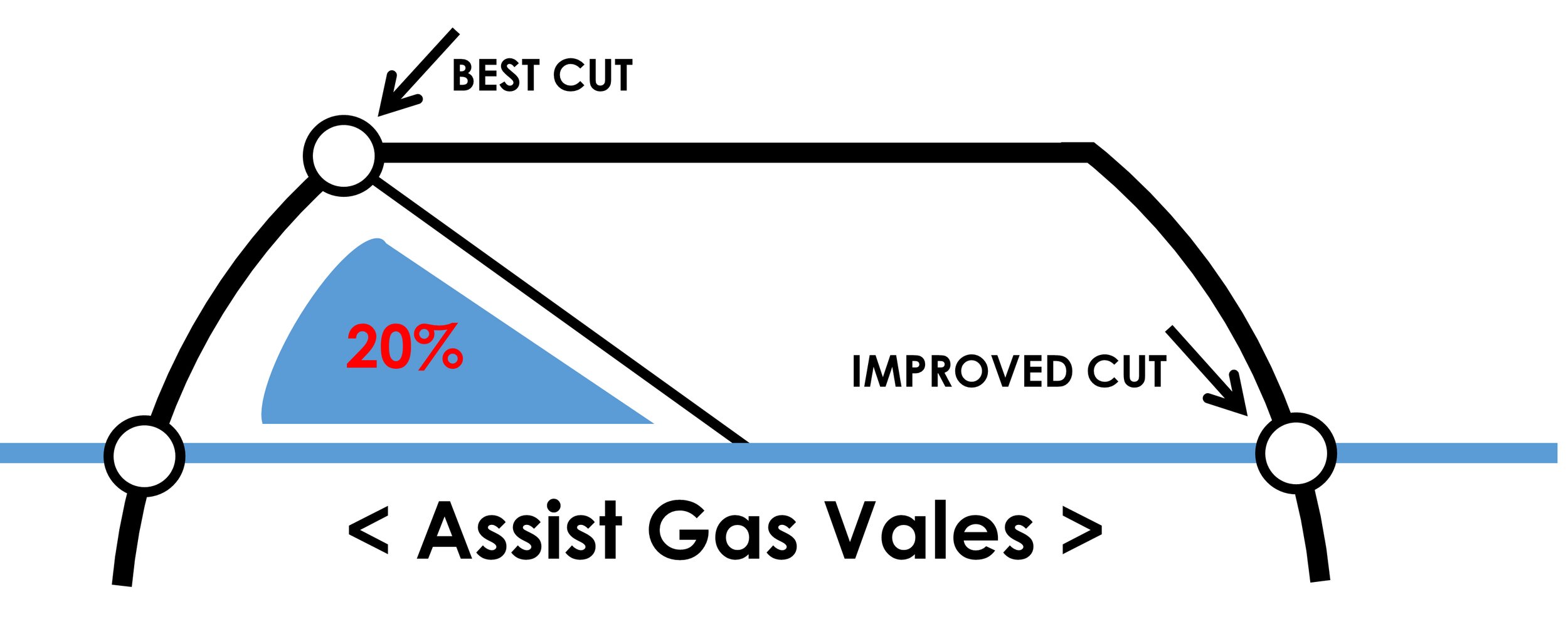
For some CO2 lasers, beam size, focus, assist gas pressure and feed rate are adjusted to improve the cutting performance. Fiber lasers may have beam profile but often this is not adjusted in normal setup. Instead focus, assist gas pressure and feed rate are used. The adjustment is made to one parameter at a time in small increments.
The key parameters for optimizing cutting performance. Beam size (CO2) focus, assist gas and feed rate
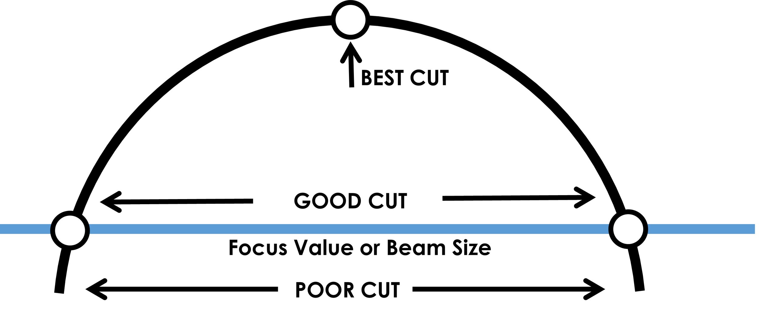
Start with beam size for CO2 lasers (that have the adjustment) and Focus for fiber lasers. After cutting a test part with default parameters increase or decrease the cut beam size or cut focus parameter and determine if the adjustment improves the part cut quality. Part quality is based on edge uniformity and dross. Dross being the material that is attached on the parts bottom edge. The goal is uniform striations and no dross.
Comparison of good quality vs poor quality cutting performance
If after your initial adjustment the cut quality is worse, take the setting back and passed the original setting. Once a trend of part improvement is found then continue with incremental adjustments until the part quality goes from good to better and then starts to decline. It is helpful to label the parts with the parameter value to create a record of parts to allow for future setting. It’s important to note that these parameters set up a bell curve where a given parameter value that is too low or too high will not improve but make the cut worse.


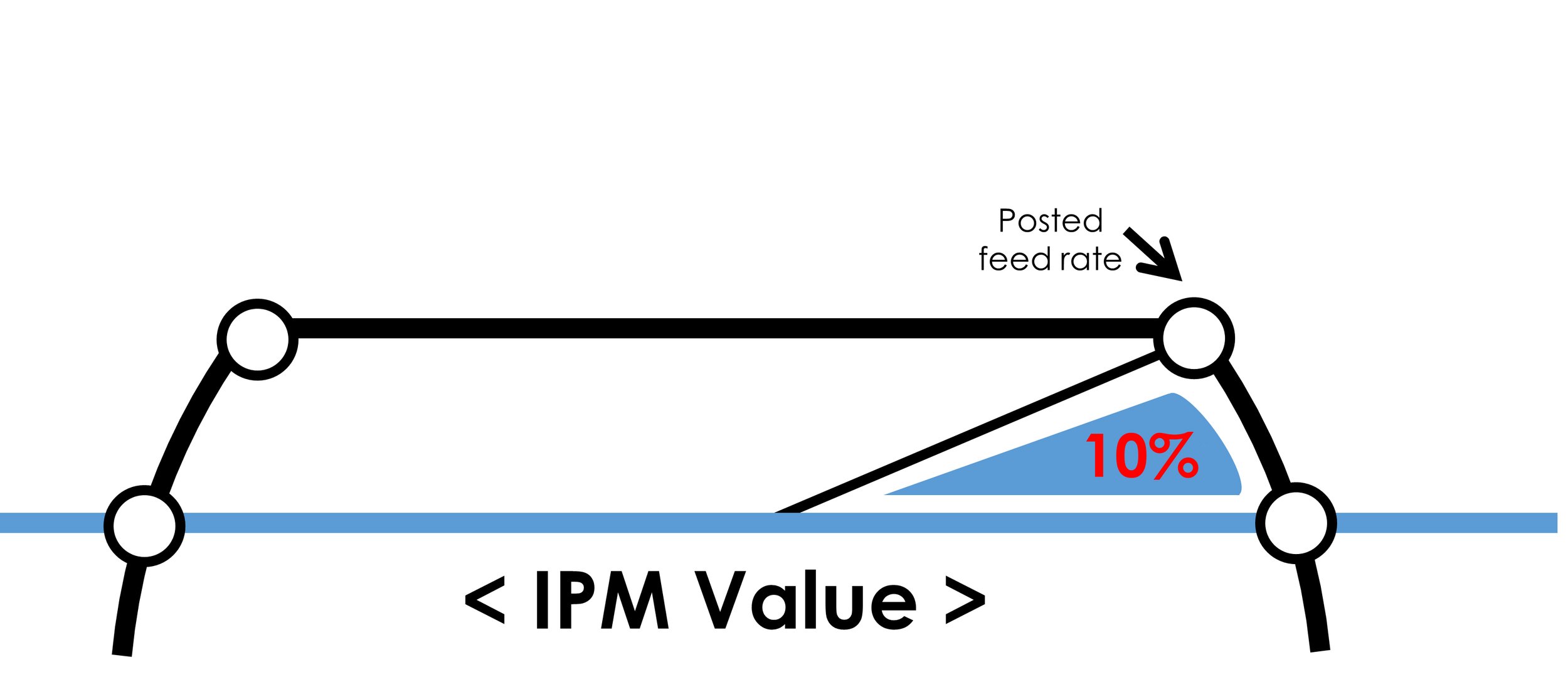
This method is repeated for focus and assist gas. The feed rate is the speed the laser processes the material. The default process parameters have a posted feed rate. This is the maximum speed that production parts should be cut. If after the beam size (co2), focus, and assist gas the part quality is within specification and feed rate is at posted then proceed to cutting a large test part, the large test part will test if the optics have thermal issues (dirty).
Troubleshooting
A large test part also forces the motion control system to cut at close or equal to posted feed rate. If the large test square cuts with in specification then proceed to production parts. If the large test part failed, check optics for cleanliness and re-check the cleanliness of the nozzle.
Verify the lens centering and recalibrate standoff. If the optics and other setup steps are fine then a reduction in feed rate may be required. Reduce by increments of 5% of the original speed. If the test parts do not contain satisfactory cut quality, be sure to verify process parameters, including material type and thickness. Contact the manufacture for assistance from service and applications department if the problem persists.
Maximizing Your Laser Investment
Lasers are one of the most widespread and versatile forms of metal cutting offering solutions for precise and complex geometry. While this equipment is an asset to any fabrication environment, the lack of proper attention given to equipment upkeep and operation will result in a waste of energy and raw materials.
Machine, Operator, and Process Operation are the three pillars that maximize laser cutting speed, quality, and efficiency. Take the time to learn and implement these areas and you’ll begin seeing a measurable and sustained return on your laser investment.


